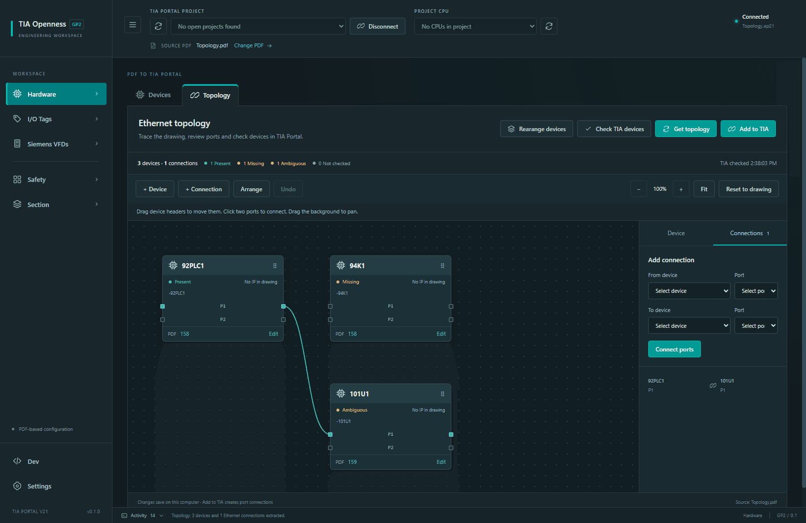
Extract hardware configuration and PLC tags directly from a supported electrical plan PDF, import them into TIA Portal V21 and automatically generate PLC code (ladder/scl) using your templates. Reduce engineering labour and costs, with estimated savings of up to 4–5 working days per PLC depending on project scope.
Estimated saving. Actual results depend on project scope.
The workflow, at a glance
Extract from PDF.
Import into TIA.
Manually configuring hardware and retyping PLC tags takes engineering time. Tia Configer reuses information already in the electrical plan PDF, helping reduce repetitive work, labour costs and transcription errors before the data enters your TIA project.
→
01Electrical PDF
Start with the electrical plan
→
02Hardware + tags
Extract directly · review the results
→
03Import into TIA
Reuse the data · save manual work
Supported drawing layouts and hardware only. Review the engineering result in TIA Portal V21.
Tia Configer in action
From the drawing to the working project.
01 / Build the project
Hardware generation
Turn the device information in your electrical plan into a TIA hardware configuration. Tia Configer reads supported components from the PDF and checks them against your installed hardware catalogue.
Review CPUs, interface modules, I/O cards and drives before selecting what to import.
Set device names and network options, then add the supported devices to the connected TIA project.
Inspect the generated racks, modules and network configuration in TIA Portal.
What you gain
A hardware configuration built from the drawing, with less repeated device entry.
Bring signal names, I/O addresses and device references out of the electrical PDF and into a PLC tag table. Keep the drawing information together while you review the extracted signals.
Find input and output tags and compare their addresses with the project hardware.
Review unresolved addresses and select the signals you want to import.
Import the selection into the target PLC and inspect the resulting tag table in TIA.
What you gain
A reusable PLC tag table without retyping each signal from the electrical plan.
Match Siemens frequency inverters in the TIA project to motors in the electrical drawing. Review the matches and prepare the motor settings together in one workspace.
Scan the project for supported Siemens drives and match them to drawing motors.
Review motor data such as rated voltage, current, power, frequency and speed, alongside ramp and control settings.
Apply supported settings to the offline project, then complete the drive checks and compilation in Startdrive. This short clip shows discovery and the settings table.
What you gain
Motor and drive settings in one overview, ready for review before application.
Group drives into machine sections and generate the repeated PLC structures from your supported templates. Keep manual-operation functions, motor communication and related alarms organised around the machine.
Find drives and their I/O, then assign selected drives to a named section.
Choose the section block structure and review the drive names, signals and telegram hardware references.
Import the generated blocks and inspect the motor calls, manual functions and alarm networks in TIA Portal.
What you gain
Consistent section blocks with the repeated control and communication connections prepared.
Organise safety signals by area and generate supported safety FB logic using the supplied library blocks. Bring area signals, feedback, doors and E-stops into a structured review workflow.
Read supported safety areas and signals from the drawing and project I/O.
Review area names and assignments, then select the areas for import.
Generate the associated blocks and networks and inspect their connections in the TIA safety program.
What you gain
Supported safety networks prepared for machine-specific engineering review and validation.
Connect supported Siemens drives to the relevant safety areas. Tia Configer reads Telegram 30 information from the existing TIA hardware and uses your reviewed assignments to prepare the safety communication.
Scan the TIA project for compatible drives and their PROFIsafe hardware addresses.
Create the supported SI control tags and assign each selected drive to its safety area.
Generate the STO_TELEGRAM30 block calls and inspect the resulting connections in the safety FB.
What you gain
Drive safety tags and block connections based on the project's hardware and area assignments.
Generation uses supported templates, library blocks and hardware configurations. Review, compile and validate the generated control and safety logic for your machine in TIA Portal before use.
A few useful details
Questions, answered.
Can I take hardware and tags directly from an electrical plan PDF into TIA?+
Yes. Tia Configer extracts supported hardware configuration data and PLC tags directly from searchable electrical plan PDFs. After reviewing the extracted data and catalogue matches, you can import the selected hardware and tags into TIA Portal V21. This reduces repeated data entry and engineering effort.
How much engineering time can Tia Configer save?+
Nidomation estimates savings of up to 4–5 working days per PLC. Actual savings depend on project scope, drawing quality, supported hardware and how closely the project fits the supplied templates. Engineering review and validation remain part of the workflow.
What can Tia Configer generate automatically?+
Supported workflows generate manual-operation functions, motor block calls and communication connections, safety FB logic and PROFIsafe communication tags and connections. Generation uses the supplied templates and libraries, your reviewed engineering data and compatible hardware. Engineers review, compile and validate the result for the machine; Tia Configer does not replace that validation.
Which TIA Portal versions are supported?+
The current implementation targets TIA Portal V21. Compatibility with other versions is not claimed. Include your TIA environment in your quotation request.
Can the application be tailored to our requirements?+
Yes. The application can be tailored to your specific requirements. Describe your workflow and the adaptations you need in your quotation request so we can discuss the scope with you.